Tuesday, March 8, 2011

In the beginning....

There was a boy. Me. I grew up riding small dirt bikes, never really lost the passion for riding but life got in the way for a few years and I was bikeless. One day my wonderful wife simply said,"just buy a damn bike already!"

She'd seen me drool at the riders every spring, knew I loved to ride.

I ended up buying a Honda Valkyrie and rode EVERYWHERE on it. Over the years I gradually made it into more of a sport tourer than Honda ever dreamed....


For comparison, here's a stocker...

Ended up in Seattle, where I met a great friend and fellow rider. He, however, rode a sportbike. A pristine Yamaha R1. After seeing what I did and could do on the Valk, we eventually switched bikes. A revelation. The big six cylinder in the valk was quick, but the R1 was altogether a different beast. I was hooked.


I'd always liked Kawasaki's reputation about the original bad ninja, the 2004 zx-10r. Twitchy, ridiculously powerful,  and always willing to bite your ass if you were stupid on it. Sounded like my kind of ride.
Finally saw the black one I was looking for at the right price. I snapped it up, and spent the next 4 years touring, ripping, cruising, monowheeling, and generally enjoying the bike immensely. A set of helibars lifted the grips from wristcrushing territory, it came with a powercommander and ignition retard eliminator. I added a pipe, a seat cowl (as it really isn't a 2-up ride), a heated gear wire harness and rode the wheels off it. The tires, anyway. This thing EATS tires. 185 crank HP, 162ish rear wheel. 480 pounds. Yeah.

My toy...

  Glacier National Park
Roadside on local twisty run.
Mount St. Helens

Like everything, though, familiarity breeds contempt. I caught myself eyeing the new crop of sportbikes every year, with more power, better electronics, etc. Problem is I really like my bike, I'm just used to it. More power, now, that'd be fun.


So, more power. 

Nitrous - naw. Expensive bottle fills, carry around a scuba tank, limited to short bursts.
Turbo - intake charge heating issues, exponential boost that makes the bike's dyno graph skyrocket with attendant driveability issues, oil/scavenge pump plumbing.
Motor work - Pricey, not a huge bang for buck as these engines are pretty optimized from the factory.
Supercharger - Very few available, drive pulley issues, but linear boost and tuneable.

 I run another blog, and back in 2007 a guy named Dan caught my eye. He'd supercharged his VFR.
Beautiful work, quality.
Here's the Post.

He uses the clever Rotrex unit, with it's unique traction fluid drive. Here's a cut-n-paste from the Rotrex site...

Key to the Rotrex supercharger's unique compactness, efficiency, low noise and reliability is its state of the art traction drive technology.

Great speeds and low noise are just some of the advantages of traction drives over traditional gear transmissions. Traction drives transmit power through friction forces between its rolling elements.
The Rotrex patented traction drive uses an elastic annulus with a small pre-span to secure contact between the roller planets and the sun shaft with a reasonable force. The patented "ramp effect" increases efficiency and reliability in the transmission by regulating the torque transfer capability on demand through self-adjusting planet geometry.

To enhance performance, the Rotrex traction drive uses a special traction fluid. These fluids are a new family of synthetic hydrocarbon oils and greases offering a series of unique performance advantages. Developed specially for its use in Rotrex superchargers, the SX100 momentarily increases viscosity under high surface pressure, enhancing the traction drive performance by securing the optimum friction between rolling elements while cooling and protecting the system.

This traction drive combined with the latest technology in centrifugal compression, characterized by high adiabatic efficiency and low noise, gives Rotrex superchargers an exceptional competitive edge over any other forced induction solution.


Imagine my surprise when in 2009 he announced he was developing a blower kit for the zx-10r!


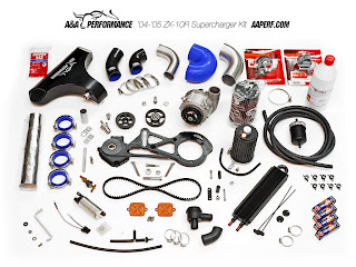
What you get...

What it does....
Yep, 220+RWHP
And, it hides under the stock fairings.


IN!

The rest of this blog will chronicle the installation of the Rotrex supercharger kit on a 2004 Ninja ZX-10r.

Monday, March 7, 2011

In preparation of the install, I built a platform that fits onto my bike lift, making an adjustable table. I HIGHLY recommend doing this or buying one, as the hours of bending/lying on concrete, twisting, cursing and generally being miserable are all now things of the past. Parts----lagbolts, two 10foot 4X6's and a 10foot 4X4, 3/4 inch plywood decking, deck screws. Two 6foot pieces of 2X4 for the outrigger/tiedowns. Four eyebolts and two ratchet straps.


Sunday, March 6, 2011

Valentine's Day present....

Got a compact but surprisingly heavy box in the mail. The kit has arrived.

The blower... Don't spin it without oil, especially not backwards.


Exquisite machined bracketry/tensioner.

CNC intake plenum. Wow.
The manual leaves the sticker placemnt as one of the last steps, but I couldn't wait....

Step one - ditching the air injection system...

The kit comes with two pretty copper anodized block off plates that allow you to remove the popping deceleration from the valves allowing air into the exhaust. Also, as the intake tract will be pressurized, you wouldn't want all that boost just being diverted into the header pipes, right. The componentry also lives where the intake piping will, so away it goes.

Remove the airbox lid, the filter, push the rubber tubes in on themselves so they tuck into the frame holes. Remove the air temp probe from the right lower corner, ziptie this down so the tip rests just above the clutch cable, in as much free air as possible.

Unbolt the airbox from the baseplate, twist it out of the frame and remove. Now pull the rubber ram air tubes out. Undo the clamps holding the baseplate to the throttle tubes, unclip the air injection hose from the upper left hand side, and remove the baseplate.

Now unplug the two harness connectors to the air valve assembly, the grey gets plugged back together and simply pushed out of the way, the white other may be left unconnected, as no ecu faults will trigger.

At this point, I removed the air valve covers and reinstalled the pretty copper plates, but the manual and, in retrospect, I recommend waiting until the radiator is removed in a few steps as space to even turn the bolts is very limited. You can see here the rightmost cover is on, the left still has the stock cap with hose barb bolted on.

Saturday, March 5, 2011

Remove the computer controlled secondary throttle blades...

Many vehicles now come with two throttles, one you physically control, and one which the computer controls. For emissions, for fuel economy, for safer acceleration, think of this system as you asking for something, and the computer deciding when and how much to give you. 

For example, you want full throttle on a cold day, with a cold engine. If you simply whack open the gas, the motor will stumble, as the airflow that was trickling in at a steady velocity now has a huge gaping maw to rush down. As a result, intake velocity drops to near zero, the engine stumbles until the airstream eventually gets back up to speed in this new size of intake. Anyone with old flatslide racing carbs knows you can't just go to instant full throttle for this exact reason,

Now, give the computer a set of throttle blades. It's manifold sensor sees this rapid change in pressure, and it decides to shut off your ham fisted attempt by closing it's own throttle, then opening it at a rate of speed that allows  some semblance of intake velocity to be maintained. The result - better acceleration by a slower opening of the throttle.

But, now we can change things. My Triumph rocket three, a 2300cc motorcycle, uses it's computer controlled throttle plates to hobble it's power output in the first three gears as someone somewhere made the decision that it would be too much power to handle. I didn't buy a 2.3 liter motorcycle thinking it would be a gentle pussycat, I hope no one does. So, out come the plates, some fuel mapping to suit, a more controlled throttle hand, and it's an infinitely better motorcycle.

Also, stock MAP sensor maps are often confused by boost, so we'll just take them out of the equation.

Thankfully, the computer plates are the uppermost ones.  Use a WELL fitting screwdriver, heat if necessary, and patience to remove the 8 tiny brass screws. Also a very good idea to stuff rags ( I spray mine with a bit of chain lube for that extra tackiness) down the intakes. Anything falling should not get past the lower plates, but twist the gas and they'll open, letting that tiny chunk of brass go get intimate with a cylinder wall. Not worth it.

You need a Power Commander

Just remembered, as you'll be pushing much more air into the motor, you need a way to meter more fuel as well. 

My bike came with a Power Commander, which is a piggyback device that messes with the ECU and fuel injectors to allow you to modify the air-fuel mixture. You can download and install maps from the powercommander website using their free software.

The stock injectors are apparently pretty good (AAperf does highly recommend sending them out for cleaning though), and with the addition of the bigger fuel pump(included in kit), the powercommander map (also in the kit on a CD) allows all the extra fuel in while on boost. 

From the  Website, 2004-2005 zx-10r owners need...

Power Commander III USB 212-411 $359.95

Friday, March 4, 2011

Radiator surgery...

If you haven't already, lose the fairings. The bellypan, both side pieces, the inner side pieces that carry the front turnsignals. I didn't remove the outer side panels under the mirrors, but it's much easier to work if you do remove the mirrors and at least loosen the panels.

Get a bucket. Really. Undo the coolant hoses, drain as much coolant as possible, remove the overflow tank on the L side of the rad, then unbolt the rad and remove. Undo the lower bolt attaching it to the front of the engine, then the upper mounts bear mentioning, the right-hand side is an actual bolt, but the left actually just slides onto a peg welded to the frame.

P.S. - all left/right annotations are from the perspective of you sitting on the bike. For example, the clutch lever is on the left side of the bike.

Scary part - cut your radiator. The inlet pipe has to be shortened to a 1/2 inch stub and flared with the included flare tool. Go slow. Deburr. Use multiple light tightenings on the tool to get the flare done and uniform.


Now that you have the rad out, you have plenty of space to install the air blockoff plates on top of the cylinder head, and change out the sparkplugs (also included).

If you've never changed zx-10r plugs, it's an ordeal. The stick coils that sit atop each plug are usually glued into place by old grime/corrosion, and they're plastic. They do simply pop-off by pulling upwards, but it takes a lot, so much so it seems like they might shatter before they release. Blow out the recess with air, the plugs are way down in the head. The hinged removal tool in the original tool bag is the way to go. A universal joint on your socket wrench helps a lot too. Adding to the fun is the fact the outermost plugs won't come out without unbolting the side frame pieces and rotating them away. Even so, it's a tight fit but they'll come. Use a piece of hose to start the new plugs by hand, imagine the horror of crossthreading a plug buried this deep in an engine. Gently.

Since I had the bike up on the lift, I went ahead and installed a new clutch. HD springs and new fiber plates. Pay close attention to the way all the plates align and come out, take pics, and then reverse the order to reinstall. The slipper ramps add to the fun, there's only a certain way to reinstall the pack so it sits right, so pay attention during removal. Soak the fiber plates in oil for a few hours to allow them to swell so your free play adjustment/takeup will be much smoother and easier.


Heavy springs on right, stock on left. Also a good idea is to lay out the bolts in the shape of the cover they came from, as often they aren't all the same length. If it'll be open for any length of time, popping them through a piece of cardboard in the covers' shape makes a good keeper, or just rethread into their respective holes.Putting a too long bolt into a crankcase casting is a recipe for a cracked block. Not good.


Thursday, March 3, 2011

Foolin' the ECU...

Install your powercommander if you need to. Basically you jack into the throttle position sensor, the injector harness, and ground to battery. Don't yet load the supercharger map, you'll need one suited to your bike for a few tests later on. Lots of maps available for free at the Powercommander website.

P.S. you have to have power to the powercommander module to upload a map. As in having the bike running or applying a 9v battery. New ones come with a 9V adapter plug, but you can make one up easily, here's the pinout....

Key must be on, kill switch on. Bike running if you don't have the 9v jacked in. now connect the mini usb to your laptop running the software program. The mini usb must be fully seated to work. Push harder than you think...it'll click.

Upload your map. Done.


Now you have to fool your ECU into thinking it's still controlling the exhaust powervalve if you bike still has one. Simply remove the cables connecting the servo motor(under the passenger seat area) to the valve. This leaves the valve open (good for boost) but still lets the computer spin it's little servo motor and think it's controlling the valve, so, no error lights.

Wednesday, March 2, 2011

Under pressure....

Get your injectors back, nice and clean? There are 4 spacers that sit between the injector body and the  injector port sealing o-rings in the kit. Put them on, reinstall the injectors onto the rail, reinstall the rail. 


Now, messing with the MAP. There's a t-piece in the kit, vacuum tubing, with a check valve at one end. Remove the vacuum tubing at the map sensor(it's the black center connector in the pic below, tubing's underneath) and t - in the check valve, reconnecting the 3rd end back to the sensor.


Now to find a place for the Blow off valve signal. Right beside the MAP sensor, between it and the throttle cables, is a small capped nipple. It's used to synchronize the throttle bodies. We'll use it to trigger the BOV. There's a necked down area just inside the nipple, used to make it easier to get a steady signal, but we want an accurate signal. So go ahead and cut the first 1/4 inch off. keep the bit in a labeled ziplock bag so you can put it inline when you sync the TB's. Deburr and attach the BOV vacuum tubing, ziptie to the nipple. The BOV will sit in the area the R intake snorkle occupied, so route the other end in that general direction.

While we're here, you'll notice the crankcase oil breather tube now has nowhere to vent. Clamp one to the small filters included in the kit to the end of the tube(one filter has a metal post-that's the one to use). Oil the K+N with the included filter oil as specified. (Lightly pink).

Tuesday, March 1, 2011

Covers and brackets and bolts....

Getting ready with the hardware...

The timing plate is held on with 5 bolts. Underneath you'll find an o-ring in it's groove. The ring will be reused in the timing cover machined into the lower portion of the blower bracket. Very little oil in here, no need to be concerned if you just changed your oil. You did just change your oil and filter, right?

You'll find the timing wheel and the M8 crank bolt. Makes sense to take a pic of the position of the wheel as the magnetic pickup is extremely strong and can pull the wheel off the splines when the bolt is out. Splines are keyed but this picture sure made me feel better when mine went clanging to the floor....

 You'll also notice my best friend in my whole toolbox, a manual impact driver. This little sucker turns a hammer blow into rotary motion, breaking free parts without cursing or damage. Cheap and effective.

There's a little o-ringed bolt up directly across from your rightmost exhaust header too. Pull it out, it'll be replaced by a longer version as well.

Monday, February 28, 2011

Building the bomb

As space is going to rapidly get tight, Make a sub-assembly of the rotrex and bracket and all the tubing/hoses.

So, away from the bike - attach supplied pre-cut oil feed lines to the rotex unit (nice that the banjo fittings are already clocked to their proper positions) using the supplied clamps. Long 29" out hose on top of unit, shorter 22" in on the front side. The rotrex has a flat base denoting the bottom of the unit to assist orientation.

 Attach the rotrex to the bracket with the 4 long tiny screws, remember the casting is aluminum, so use blue threadlocker and don't overtorque.

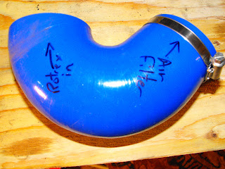
There's an asymmetric 135 degree elbow that clamps to the inlet, pointing virtually straight up with the opening facing the right side of the bike. (I marked mine for clarity)

Now clamp on the 90 degree outlet silicone tube, pointing directly across the bike to the left side. 
The kit comes with a complicated looking piece of precut heat shielding, practise several times with the backing still on until it makes sense, then peel and stick. Make sure your clamps are secure as they'll be buried under the shielding.


Sunday, February 27, 2011

Blower, meet bike...

Time has come. The crank connector is a critical piece. First, massage the o-ring into the groove of the "new" timing cover, aka the lower part of the bracket. Now it gets complicated. You'll need two kinds of  Locktite, a red 266 and the heavy duty green 609 retaining compound.


First CLEAN everything with a spray carb/brake cleaner to remove any oils.

The backside face of the crank connector gets a dose of red where it snugs up against the timing wheel, as do the threads on the new longer crank bolt.

The 609 gets laid in a thin bead between the outer diameter of the crank connector and the inside of the inner high speed bearing race. Push the connector through the bearing and apply a thin ring, then push it back through and redo the same. The idea is to get the connector and bearing race to lock together without getting any compound in the bearing itself.


Fit the bracket to the bike, making sure rubber sheet atop motor is out of the way and the clutch cable is ziptied to the ignition pickup and both are routed behind the bracket.

Just barely start the timing cover bolts and the longer cam chain guide bolt. Carefully push the crank connector assembly toward the crank, then bolt the pulley bolt into the crank end, ensuring the timing wheel remains in place. Torque to 45ft/lb.

Snug the timing cover bolts to 9ft/lb, the guide bolt to 18ft/lb. Also in the kit is a socket head bolt with a spacer and nut. Both nut and spacer have a flat ground on them. This assembly bolts through the bracket into an existing engine boss. Blue locktite. You can see half the bolt behind the idler pulley above.

Saturday, February 26, 2011

Toobin'

OK, there's not a lot of space and a lot needs to go in. Wish I had smaller paws. 

Installed the intake plumbing with it's integral BOV tubing, added a silicone elbow to the top. The ninja now gets it's air from below the steering head. 

The intake plenum is next. The manual has a cool pic of how all the silicone hose clamps should be clocked for install, but my mitts just couldn't do it. The incredibly tight fit meant I eventually removed the bottommost clamps entirely, then fished each through individually as the silicone finally was persuaded into place. 


This was honestly one of the toughest portions of the install, the tolerances are minimal. There was a lot of cursing and deadblow mallet use, but I would truly have been undone if not for....

Yep, a tiny pick set. This and his friends allowed me to get in and around the silicone without tearing, gently coaxing them to seal like you'd roll a tire onto a rim.

So glad that's over.


Connected front inlet to intake pipe, added the BOV to it's runner and attached the vacuum line and it's own cool little filter.


Friday, February 25, 2011

Coolers...

Getting the rad ready to go back in, completing the rotrex oil circuit....

The kit comes with a longer bracket to space the bottom of the radiator further from the engine. Use red locktite to secure this to the block, but don't do as I did in this pic...leave the rad unconnected for now.

The kit also comes with a series of grommets and bracketry that allows the top of the rad to move down and forward. Basically you're building a little "briefcase handle" atop the rad. It then mounts to the bikes original top points using this handle, allowing a swing motion. Here's a pic of the silver "drop bracket" on the left side...


Mount the top of the rad to the bike.


The Rotrex traction fluid needs a circuit to ensure the unit gets a constant supply of cool filtered oil...

All the lines are precut, barb fittings preset, clamps all provided.

Lines... the two long lines from the rotrex are ziptied together, and are looped behind the radiator after getting a wrap of heat shielding where they pass near the exhaust. The hot oil leaving the rotrex loops up over the left top of the rad and falls into the provided oil cooler, which uses specialized ties to simply clamp it to the left front of the existing rad. Now cool, the oil returns to the reservoir, where it has a minute to defoam through the blue breather cap. P.S., don't clamp this hose on without bleeding the system, the lines are extremely tough to remove from their fittings. The reservoir is held upright by one screw, tapped into the top of the left frame rail.

It leaves the bottom of the tank, passes through a filter, and on back to provide boost happiness. Easy.

The system must be primed before use, though. Use either compressed air into the breather hole until you see return fluid, or use a brake bleeder to suck fluid through the system. I'm afraid of trapped air bubbles in fluid lines, so I used the vacuum method. No problems.

Install the aluminum intake elbow onto the silicone tubing and clamp. Realize the filter will live under the right fairing panel just above the radiator cap to visualize the necessary angles.

Reinstall upper small coolant lines, attach to lower mount, and tighten upper mounting bolt.
The right upper hose (the one that used to connect to the part that was cut and flared) is now too short to make the trip. Cut the hose just above the timing cover uppermost bolt and splice in the aluminum tubing. 

Now it reaches. You'll have to cut an angle at the end of the hose somewhat to get a clampable match onto the flared barb.

Thursday, February 24, 2011

Got compression, air,spark....

Need fuel.

The 10r's fuel pump is not a burly thing, multiple reports of failure, barely adequate flow rates, and expensive to replace when it does fail. But, a much more powerful pump fits in the same space with minimal modification. It's included in the kit.

It's a Walbro 250. Here's the difference....


The in-tank fuel pump housing. The yellow highest wire is the low-fuel sensor, the golden "top hat" is the pressure regulator. Dissambly is easy, the two side screws and the two electrical connections get undone, then the whole pump slides out of the "sump". Further discerning pulling separates the pump itself from the housing.

As the new pump is taller than the stock one, both the white regulator retainer clips' tail and the regulator tail itself must be shortened. Dremel. There are several o-rings around the various inlets, use a flashlight to ensure you remove/replace all as necessary otherwise an errant one can block fuel flow.
The small white clip in the center of the pic applies pressure to the pump outflow tube, it needs a bit of dremel work as well to sit flat on the new pump, as the tabs are slightly different. The base of the stock pump is treated to a rubber gasket, this gets tossed. The white retaining clip goes back on, though. Ensure the new pump and wiring harness are seated as fully as possible. Of note, the fuel filter screen that comes with the kit is particularly difficult to coax into the sump. Slow methodical corner by corner will allow it to descend, though.

Ensure the wires are routed behind the new connector and as close to the pump as possible as it's a tight fit to get the assembly back in the tank. Also ensure that your connections are secure and correct as they'll be in a fuel tank a long time. 

The regulator retainer (white clip) must be secured with a zip tie to ensure the regulator doesn't pop out. Use the smallest diameter tie possible as again it's a very tight fit to get it into the tank.

Clean/replace the big o-ring if needed, then torque to 7ft/lb with red locktite. Reinstall tank on bike, bolt rear down, prop front. Connect electrical,vent and fuel lines.

Wednesday, February 23, 2011

Ready? Fire?

O.K., acid test time. Oil? check. Oil in rotrex? check. Fuel? check. Coolant? Not yet...but only a test fire....

Key on. Lights on. Kill switch on. Weird. No sound from the fuel pump. Flashing "low fuel" light. In neutral. Hit the starter. Motor turns over, doesn't fire. Again. Nope. 

GRRRR.

Not good. Can't figure it out in my groggy state. No error codes when I check dealer mode, the bike will prime the lines and run if I jumper in 12v direct to the fuel pump connector.

Fuel pressure about 42psi according to my tester. Won't hold residual pressure in lines.

Multimeter everything. The fuel pump is supposed to turn on with the key, run for 3-4 seconds to prime the lines, then shut off until the bike starts. So, the voltage should be battery voltage for those four seconds, followed by 0. I'm getting constant battery voltage at the pump. Not enough amperage to run the pump, though.

Put the old pump back in, same problem. Put the new pump back again, same issue.

After messing with the fuses, the relays, unplugging and replugging every connection I could touch, I was getting frustrated.

Then, the flashing low fuel light started triggering my thoughts. There was plenty of gas. What about a defective sensor? Did I break it in my multiple removals?
I went looking for low fuel sensor voltages in the manual. HMMM.

I'd inadvertently attached the low fuel sensor lead to the positive fuel pump lead. Replaced them, bolted it up, fixed. Pump primes as it should.

Hit the starter. It Lives!!!!!

Maybe I should wear a helmet everywhere.

Tuesday, February 22, 2011

Loose ends...

It runs! I'm a happy guy. 

Filled and bled the cooling system with "Engine Ice".

Put on the belt. Adjusted Idler tension until it read the 55-65lbs with the supplied tension checker. Torqued bolt to 40ft/lbs. 

Nothing I've done so far has made me more happy that finally tensioning that cogged belt.

Dragged the laptop into the garage, fired up the powercommander software, threw the included blower map cd in. Jumpered a spare 9v, uploaded the new map without an issue. Will get it dynoed and personally tuned, but it's more than ok for now.

Squeezed the preoiled intake filter to clear the right fork leg a bit, clamped it on. 

Rechecked the rotrex oil level, added some fluid to get to the prescribed 1/2 mark. Bolted up the tank, reinstalled my dampener, put the seats back on.... oh.....

Opened the garage door to find this.

Yep, snow. In Seattle.

It idles well, tracks straight belt wise, revs monstrously to 6500rpm (100km breakin period you know).

Go away snow.

Monday, February 21, 2011

If I said you had a beautiful body....

One of the cool things is that the whole thing hides under stock fairings. They need a little modding/spacing out but it's virtually unnoticeable even to other riders until you see the belt drive peeking out.

First, the inner panels alongside the front wheel that carry the turnsignals need some trimming to clear the spaced forward rad., the template is supplied. I used a dremel tool with a spiral bit designed for wallboard. At med high speed you can draw fine shapes with it. Leaves a nice edge too.

The bellypan needs the rounded triangle hole enlarged to clear the crank pulley. This is my freehand result...


The right mid fairing needs some contouring done to allow the modified rad hose to run alongside it, mostly slicing off lips. In this pic, the piece closest to the camera folded 90 degrees to the main panel needs to go away.
The kit comes with a small assortment of spacers that push the right fairing out 1-2 inches, yet keep it tucked in at the bottom to maintain ground clearance. I did have to trim around my frame sliders, but it too was minimal...


OK, stay tuned for the ride, videos, reports, etc. It begins.